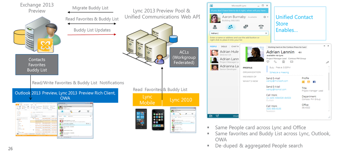
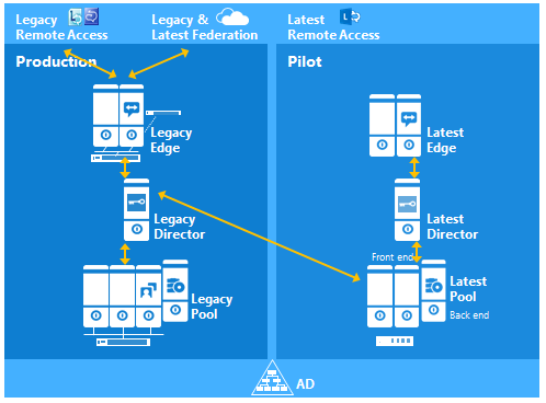
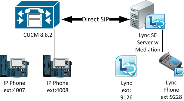
With the release of Exchange 2013 CU1, we can finally deploy the Unified Contact Store (UCS) into an existing Exchange2010 SP3 environment. This is because Exchange2013 is required for UCS and the GTM version of Exchange2013 did not support coexistence with previous versions of Exchange. To recap, UCS enables users to store all contact information in Exchange 2013 so that the information is available globally across Lync, Exchange, Outlook, and Outlook Web Access. Without UCS, Lync2013 clients cannot change or upload their photos. Below is the UCS architecture diagram for reference: 
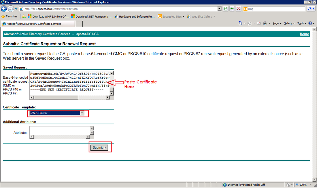
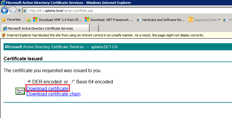
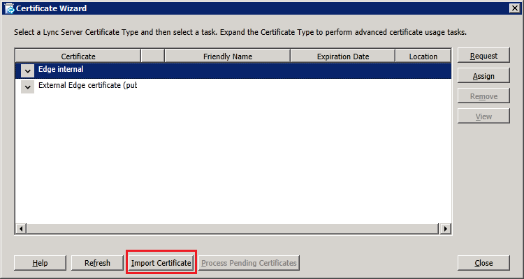
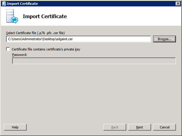
Deploying Exchange2013 CU1 itself is beyond the scope of this article and the steps are provided in Technet. For existing Exchange2010 environments as in the case of this lab setup, upgrading to Exchange2010 SP3 is required which also performs the prepare AD schema, thereby eliminating the need to run setup.exe /PrepareSchema using Exchange2013. After deploying Exchange2013 we also need to run the post-install steps as described in here. Most notably would be the need to assign a CA issued certificate for the CAS role as Exchange2013, like it's predecessors, by default uses a self-signed cert which Lync2013 will not recognize. Once the prerequisites are done, enabling unified contact store in Lync Server 2013 does not require any topology settings. All that's needed is that the Unified contact store policy is enabled (default is enabled), user's mailboxes have been migrated to Exchange2013, and user log in with using the Lync 2013 rich client at least once.
0 Comments
The Polycom CX600 is a Lync Phone Edition (LPE) device that is optimzed for Lync2010 and Lync2013 environments. As briefly mentioned in the KB Article for the January2013 CU for LPE devices, this new firmware update actually allows the phones to support Lync Online and Office365. This article descibes how to configure the CX600 for use in Office365 Plan E4 in a lab environment. For Lync On-Premise scenarios, fellow MVP Jeff Schertz has written excellent blogs on how to configure these phones for Lync available here. Since the phones require users to be enabled for Enterprise Voice, only Office365 Plan E4 or Lync Online Plan 3 can be used with the Lync Phones as only these plans include the Enterprise Voice" feature equivalent in Lync On-Premise, which is refered to as "Lync-to-Phone" in Lync Online. In US and Canada, the "Lync-to-Phone" PSTN connectivity is provided by service provider JahJah and this service is not currently available anywhere else in the world. For Office365 users outside US and Canada, PSTN connectivity can still be achieved by deploying an On-Premise Lync environment with PSTN connection via a qualified gateway while still using Lync and Exchange Online in the cloud. These are refered to as Hybrid Lync Server deployments. Details on how to configure phones for these hybrid scenarios will be covered in a future article. In this article we will not configure any PSTN connectivity.
Getting Started: Configuring Exchange Online for UMTo allow the CX600 phones to retrieve VoiceMail and Call Logs, the Exchange Online service must be configured for Unified Messaging UM). To get started, navigate to the Exchange Admin Center and select Unified Messaging on the left tab. Then Click on the "+" button to add a new UM Dial Plan as shown below: On the new UM Dial Plan window, we enter a desriptive name for the dial plan followed by the Extension length which would be the number of digits in the full E.164 number excluding the "+". For eg if the country code is 65 followed by another 8 digits, then extension length would be 10 digits. Next select the "SIP URI" Dial plan type and select the desired audio language. Sample screen shot is shown below:
In a previous article, we discussed the steps to deploy a new Lync2013 Edge server into a Lync2013 FE pool that was coexisting with a legacy Lync2010 Pool with Lync2010 Edge. Users homed on the Lync2013 FE pool continued to use the legacy Edge server for remote access and federation. Although having both the legacy Edge and the 2013 Edge providing remote access is possible, such a configuration would be more difficult to manage and moreover, only one Edge can be used for federation. In this article, the steps to migrate completely to the new 2013 Edge will be discussed. Users still homed on the legacy Lync2010 FE pool as well as those homed on the new Lync2013 FE pool will use the new 2013 Edge for Remote Access and Federation. The end result should look like the diagram below: In a production environment, changing the federation route and media traffic route requires downtime for the Lync Server 2013 and Lync Server 2010 Edge Servers. Federated access will be unavailable for the duration of the outage. Configure the Lync2013 FE Pool to use the new 2013 EdgeIn topology builder, edit the properties of the Lync2013 FE and associate the Edge pool with the new 2013 Edge:
In a previous article, the steps to introduce a Lync2013 Standard Edition FE server into an existing Lync2010 environment was discussed. That existing Lync2010 environment also had an Edge server for remote user access and federation. This article has 2 parts: Part I describes the tasks to connect the Lync2013 FE server to the legacy Lync2010 Edge pool. Part II then describes how to deploy a Lync2013 Edge server in parallel with the legacy edge. A separate article will be posted later to discuss how to completely migrate all users to the Lync2013 Pool and decommission the legacy Lync2010 components. Part I: Connecting the Lync2013 FE Server to the legacy Lync2010 Edge PoolIn order to use the federated route that is being used by Lync2010, Lync2013 must be configured to use this route. This is a simple 2-step process. In the Lync2013 Topology Builder, right click the Site and select "Edit Properties..". In the Edit Properties window, click on the "Federation route" in the left pane. Then select the "Enable SIP federation" checkbox and choose the legacy Lync2010 Edge server from the drop down as show below: Next, right click the Lync2013 FE node and select "Edit Properties". In the "Edit Properties" select the "Associate Edge pool (for media components)" check box and choose the legacy Edge from the drop down list as shown below: Finally publish the topology and wait several minutes for the topology to be replicated across all servers. Then verify that users homed on the Lync2013 FE can federate with external users via the legacy Edge. At this stage, all remote access and federation capabilities are routed via the legacy Edge (Director shown for illustration only) as shown in the diagram below: Part II: Deploying Lync2013 EdgeTo deploy the Lync2013 Edge in parallel with the legacy environment, there are 5 steps to be performed: Step 1: Define the new Edge pool in Topology Builder Step 2: Install Prerequisite software for Lync2013 Edge Step 3: Deploy the Edge server components Step 4: Request and Assign Certificates for Edge Step 5: Start Edge Services 1. Define the new Edge pool in Topology BuilderFirst, create a DNS A record for the Edge internal NIC. In this lab we use edge2013.apbeta.local as the FQDN of the internal NIC and an IP of 10.222.202.94. The 3 external FQDNs for Access, Web Conferencing and AV are access13.apbeta.local, webconf13.apbeta.local and av13.apbeta.local respectively with IP in the ranges 10.250.27.[146-148]/25. We need to input these parameters when preparing the Edge server in the next step. In the Lync2013 Topology Builder, expand the "Lync Server 2013" node and right click on the "Edge Pool" node. Select "New Edge Pool..." to start defining the edge pool properties: In the "Define New Edge Pool" window, click "Next". Since we are installing a single Edge server for this lab, select "Single Computer Pool" and enter the internal FQDN of the Edge server then click "Next": In the "Select Features" window, do not enable Federation or XMPP federation. Federation and XMPP federation are both currently routed through the legacy Lync Server 2010 Edge Server. These features will be configured in a later phase of migration. For now, just click "Next": Next, select the appropriate IP options and enter the 3 FQDNs of the external interface as defined earlier: Next, enter the Edge internal IP address and click "Next" followed by the external IP address and click "Next": Specify the next hop server to be the legacy Lync2010 FE at this stage. Migration to the new Lync2013 pool will be done later: No association of a pool with this Edge pool is selected at this time. External media traffic will continue to route through the legacy Lync2010 Edge. This setting will be configured in a later phase of migration: Publish the topology and verify successful completion: 2. Install Prerequisite software for Lync2013 EdgeHere we prepare a Hyper-V VM with 2 NIC cards and install Windows Server 2008R2 SP1 Standard Edition Full install. We then configure one NIC card for the Edge internal interface and assign the IP 10.222.202.94/24. We also configure the Primary DNS Suffix of this computer to apbeta.local and do not set a default gateway, leaving the adapter DNS settings empty. Lastly, we create persistent static routes on the internal interface to all internal networks where Lync clients or servers running Lync Server 2013 reside and edit the HOST file to contain a record for the next hop Lync2013 FE server which was configured as the Edge Server next hop address in Topology Builder. The other NIC card is for the external interface and we configure 3 IP address 10.250.27.[146-148]/26. The internal and external subnets must not be routable to each other. We also configure the default gateway on the external interface and would normally point to an external DNS. Since we do not have a DNS server in the DMZ in our lab so we will use host files (shown later). On the Windows2008R2 SP1 server, do the following in sequence: 1. Run Windows Update to get all the latest hotfixes and patches. 2. Install .NET Framework 4.5 from http://www.microsoft.com/en-us/download/details.aspx?id=30653 3. Enable Windows Powershell Integrated Scripting Envrionment (ISE) from Server Manager->Add Features 4. Install WMF3.0 from http://www.microsoft.com/en-us/download/details.aspx?id=34595 using the correct file. For Windows 2008R2 SP1 it should be Windows6.1-KB2506143-x64.msu 5. Install Windows Identity Foundation from http://go.microsoft.com/fwlink/p/?linkId=204657 using the correct file. For Windows 2008R2 SP1 it should be Windows6.1-KB974405-x64.msu 3: Deploy the Edge server componentsBefore installing the Edge components, we need to export the topology into a file so we can import into the Edge server. In the Lync2013 Lync Management Shell, run the following cmdlet: "Export-CsConfiguration -FileName c:\config.zip" and copy this file to the Edge server. Now insert the Lync2013 Server installation DVD into the VM and double-click the icon to autorun the setup. Click Yes when prompted to install Microsoft Visual C++ Redistributable, In the next dialog box, accept the default Installation Location and click "Install". Accept the terms in the license agreement and click "OK" to proceed. In Deployment Wizard click "Install or Update Lync Server System" After determining the deployment state, click "Run" in "Step 1. Install Local Configuration Store": In the Configure Local Replica of Central Management Store dialog box, choose "Import from a file (Recommended for Edge Servers)" and specify the location of the exported topology configuration config.zip file and then click "Next": Click "Finish" when the Local Configuration Store installation is completed. Next click in "Run" in "Step 2 Setup or Remove Lync Server Components". In the "Setup Lync Server Components" wizard, click "Next". Then and allow the wizard to complete. There's no input required in this step as the wizard will read the configuration file and install the necessary components. Click Finish to complete the wizard when finished: 4: Request and Assign Certificates for EdgeFirst, download the Root CA Chain from the internal CA website, save the chain .p7b file locally and then use the certificates mmc to import the .p7b file into the Edge server's local computer Trusted Root Certification Authorities store: Next, on the Lync Server Deployment Wizard, click on "Run" in "Step 3 Request, Install or Assign Certificates" and in the Certificate Wizard, select "Edge Internal" click "Request": In the Certificate Request wizard, choose to "Prepare the request now, but send it later..." and in the next screen, enter a local file to save the request and then click "Next", enter a Friendly Name, then the Orgnization info, Geographical info, leave the remaining screens as default until the wizard is completed: Next navigate to the internal CA website and click on "Request a certificate", followed by "advanced certificate request" and then "Submit a certificate request by using a base-64-encoded CMC or PKCS #10 file, or submit a renewal request by using a base-64-encoded PKCS #7 file.". In the web browser paste the contents of the certificate request file created earlier into the text box and click Submit as shown below: Next, download the certificate and save locally to a file: Then, back on the Lync Certificate Wizard, click on "Import" to import the downloaded certificate file: In the "Import Cerfificate" wizard, select the saved certificate file and click "Finish" to completed the wizard: After importing the certificate, we need to click on "Assign" in the certificate wizard: In the Certificate Assignment wizard, we click "Next" and "Finish" to complete the assignment: After getting the internal certificate for the Edge, we now focus on the External Edge. The process is similar and not all the steps will be repeated, but only the differences will be highlighted. On the Certificate Wizard, select "External Edge certificate" and click "Request": The remaining steps are similar to those for the internal certificate. Of course a different Certificate Request File should be specified as well as a different Friendly Certificate Name. But the Private Key must be marked as exportable as shown below: In the Subject Names windows, note that the two SANs are already added automatically: An additional step is required to select the SIP domain to be added to the SAN list: In the next step, the lab does not require any additional SANs. Proceeding with the Request Summary page will allow us to generate the CSR which is saved to a file c:\extreq.req Using the same method as the internal certificate, submit the request to the CA and save the certificate. Then import the certificate using the certificate wizard with the "Certificate file contains private key"checkbox cleared: Click next to continue and complete the wizard, verifying that the certificate was imported successfully. Back on the certificate wizard, select "External Edge certificate" and click "Assign": In the "Certificate Assignment" window click "Next". In the "Certificate Store" window, select the external certfiicate and click "Next": In the "Certificate Assignment Summary" window, click "Next". Then verify successful assignment and click "Finish" to end the wizard. Both internal and external certificates should now have a green tick as shown below: 5. Start Edge ServicesFinally, we start the services by clicking "Run" at the "Start Services": Verify services are started successfuly and click "Finish" to end the wizard. At this stage, we have introduced a Lync2013 Edge into the mixed environment but are still using the legacy Lync2010 edge for all external access and federation services. In a future article, we will migrate the Remote Access and Media Traffic for Lync2013 users to use the Lync2013 Edge services.
After several days of configuring and troubleshooting, finally got Lync integration with Cisco CUCM 8.6 working in a lab environment. This article walks through the steps taken and some of the problems encountered. Microsoft has a document that provides step-by-step guidance on the integration available for download here which this article is based on. The steps in the document will not be repeated in this article, rather only the specific implementation in the lab and any deviations will be highlighted. The exact version of CUCM used in the lab is 8.6.2.22900-9 which is slightly newer than the 8.5.1.11900-211 version that the document is based on. Nonetheless all the steps in the document are still valid and can be used with some minor changes which are described in this article. Below shows the diagram for the lab setup: The Cisco phones have extension 4xxx while the Lync clients have 9xxx. Lync 2010 server is running CU6 with colocated mediation server and media bypass enabled. CUCM users and Lync users should be able to call each other with 4 digit extensions. Below shows the 2 Cisco IP phones registered to CUCM: Let's recap some CUCM Basics before beginningCUCM Dial Plans typically consists of Directory Numbers, Route Patterns and Translation Patterns: Directory Numbers (DN) are internal extensions assigned to phones lines, response groups, voicemail attendants etc. Route Patterns (RP) are used to match numbers for routing to external PSTN gateways or SIP Trunks. Translation Patterns (TP) are normalization rules used to manipulate dialed digits before routing a call. When a user dials a number, the digits are send to CUCM which then uses the DN, TP and RP to perform a Digit Analysis process to determine whether to ring another user or send the call to a SIP Trunk or gateway. In Lync we call this Reverse Number Lookup (RNL). To control whether a user has permissions to ring another user or utilize a route to make PSTN or trunk calls, CUCM uses Partitions and Calling Search Spaces. Partitions are collections of DNs, RPs and TPs that divide the Dial Plan into segments. For example, Partition Chicago contains directory numbers for users in Chicago and the Route Patterns and Translation Patterns for that locale. Any DN, RP or TP that is not assigned to a paritiion belongs into the Null Partition. Calling Search Spaces (CSS) are an ordered list of Partitions grouped together and assigned to devices. Numbers in a partition are only reachable by devices that are assigned a CSS that contains that partition. Digit Analysis will only process DNs, TPs and RPs within the CSS assigned to the calling device. Therefore CSS controls what numbers a device can call. CSS can be assigned to phone lines, phone devices, gateways and trunks. Numbers not assigned to any Partition belong to the "Null Partition" and are reachable by all devices. A simple illustration is as follows. If Bob wants to call Ann, then Bob's CSS must contain a Partition that Ann's Directory Number belongs to. Similarly, if Bob wants to make a IDD call through a gateway, Bob's CSS must contain a Partition than the Route Pattern for that gateway belongs to. In some sense, CSS's are like PSTN Usages in Lync. Media Resource Groups (MRG) are logical groupings of media resources such as conference resources, transcoder resources, MOH servers and Media Termination Points. A Media Resource Group List (MRGL) is simply a prioritized grouping of MRGs. The most common use of MRGs and MRGLs is to restrict media resource usage on a geographic basis. For example, an MRGL can be assigned to a phone at a remote location that only allows it to access local conference bridge resources so that WAN bandwidth is conserved. Configuring CUCM SIP TrunkWith the baisc CUCM concepts covered, we can proceed to configure the SIP Trunk. As per steps provided in the document, we need to do in the following order: 1. Create SIP Trunk Security Profile 2. Create SIP Profile 3. Create SIP Trunk 4. Create Route Pattern 1. Create SIP Trunk Security Profile In the lab, we created the SIP Trunk Security Profile with no deviations. The screen capture is shown in the diagram below: 2. Create SIP Profile Next, for the SIP Profile, we created as per documentation as well with no deviations as shown below: 3. Create SIP Trunk Before creating the SIP Trunk, we need to define a few more items. The first is the Media Resource Group (MRG)which will then be added to a Media Resource Group List (MRGL). The MRG is defined under Media Resources->Media Resource Group and is shown below: With the MRG defined we then add it into a MGRL created under Media Resources->Media Resource Group list as shown below: Next item to define before creating the SIP Trunk would be the Calling Search Space (CSS) under Call Routing->Class of Control->Calling Search Space. Our CSS is defined as shown below: The CSS shown above contains the Route Partition named "LyncPartition" which is defined in the Directory Number (Line[1]) of the Phone Configuration of the two Cisco IP Phones along with the CSS "Outbound to Lync": The Route Partition "LyncPartition" contains the necessary translation pattern to translate the incoming number from Lync to CUCM extensions. Translation Patterns can be defined in Call Routing->Translation Pattern and our translation pattern translates E.164 number (without + sign) coming from Lync to a 4-digit CUCM extension: In this lab, we are translating a 4-digit dialed number from Lync to E.164 for CUCM without the + sign. We will be using the Trunk Configuration to do it as shown later. Now we are ready to create the SIP Trunk. This is done under Device->Trunk and we have defined the SIP Trunk as shown below: 4. Create Route Pattern We also need to create Route Patterns for CUCM users to call Lync users using 9XXX 4-digit extensions. This is defined in Call Routing->Route/Hunt->Route Pattern as shown below: Lync SIP Trunk Configuration for CUCMAs per the MS documentation, these are the tasks to configure Lync Server to perform Direct SIP integration with CUCM: 1. Add CUCM to the Lync topology. 2. Configure the dial plan. 3. Add voice policy and route. 4. Add Trunk configuration. 1. Adding CUCM as a PSTN Gateway using Topology Builder This is fairly straighforward process of using Topology Builder to a new PSTN Gateway using the IP address of CUCM with port 5060 over TCP: Next we edit the properties of the Mediation Server and add the newly created gateway into the mediation pool: We then published the topology and made sure there we no errors. 2. Configuring the Dial Plan We add a normalization rule to the relevent Dial Plan to catch CUCM 4-digit extensions starting with 4XXX. We will perform no translations: 3. Add voice policy and route Now we edit the Global Voice Policy to add a new PSTN Usage as shown below: The actual Route matches any dialed number starting with 4 and routes the call to the CUCM as shown below: 4. Add Trunk configuration. Finaly we add a new Trunk Configuration in Lync. As per the MS documentation, we create a new Pool Trunk Configuration and select the CUCM PSTN Gateway with Encrpytion support set to Optional. The documentation also specifies enabling Media Bypass and disabling Refer Support followed by running powershell cmdlets to set RTCPActiveCalls and RTCPCallsonHold to false and EnableSessionTime to True: The remaining steps in the document of enabling Media Bypass in the Global Network Configuration and setting the MediaConfiguration to SupportEncryption are straightforward and are not repeated here. Simply follow the steps in the document. Q850.1 ErrorsWe were getting call failures in the beginning and Lync Server's SIP Trace shows errors as below: ms-diagnostics: 10404;source="LYNC2010.uclab.apac.local";reason="Gateway responded with 404 Not Found (User Not Found)";component="MediationServer";SipResponseCode="404";SipResponseText="Not Found";sip-reason="Q.850;cause=1";GatewayFqdn="10.222.202.152" ms-diagnostics-public: 10404;reason="Gateway responded with 404 Not Found (User Not Found)";component="MediationServer";SipResponseCode="404";SipResponseText="Not Found";sip-reason="Q.850;cause=1" Reason: Q.850;cause=1 ms-trunking-peer: 10.222.202.152 ms-endpoint-location-data: NetworkScope;ms-media-location- Based on the ITU Recommendation Q.850, this error is due to "Unallocated (Unassigned) number". Later we found this to be due to the Device Pool that the CUCM Phones were in did not contain the correct CSS. Device Pools are defined under System->Device Pool. After selecting the correct CSS in the Device Pool, then all was fine and we are able to get calls to/from Lync and CUCM working: Calling ExperienceAs mentioned in the beginning, both CUCM users were able to call the Lync users using 4-digit extensions. It also happens that the CUCM users were signed in on phones capable of doing video. The Lync users were signed in on Polycom VVX600 phones running firmware 4.1.2.22625. The 9951 Cisco phones are capable of video when calling each other, but not with Lync due to the way Lync handles calls via the PSTN Gateway which only advertises audio capabilities in the SIP INVITE: TL_INFO(TF_PROTOCOL) [0]0A10.1A24::02/13/2013-08:53:41.995.001d4d01 (S4,SipMessage.DataLoggingHelper:sipmessage.cs(686))[4068699085] <<<<<<<<<<<<Incoming SipMessage c=[<SipTlsConnection_1099E63>], 10.250.27.54:5070<-10.250.27.67:63337 INVITE sip:4007@10.222.202.152:5070;user=phone;transport=tls;maddr=lync2010.uclab.apac.local SIP/2.0 FROM: "Brennon Kwok" <sip:Brennon.Kwok@uclab.apac.local>;tag=E1DEB21B-9B674EF4;epid=0004f2ae4b0d TO: <sip:4007;phone-context=sgdialplan@uclab.apac.local;user=phone> CSEQ: 1 INVITE CALL-ID: 5b36d69dccfe4b1b3eae46c179ae4b0d MAX-FORWARDS: 69 VIA: SIP/2.0/TLS 10.250.27.67:63337;branch=z9hG4bK85B5D519.F2C2544BA9E4FC96;branched=TRUE VIA: SIP/2.0/TLS 10.250.27.13:35425;branch=z9hG4bK682046e83E0C5E49;ms-received-port=35425;ms-received-cid=540C500 RECORD-ROUTE: <sip:EEPool.uclab.apac.local:5061;transport=tls;ms-fe=LyncEE1.uclab.apac.local;opaque=state:T;lr>;tag=92BEAF9383A0D959E9B155C0472C72CB ALLOW-EVENTS: conference,talk,hold CONTACT: <sip:Brennon.Kwok@uclab.apac.local;opaque=user:epid:4WChQ84TxlyATEooiiwYcwAA;gruu> CONTENT-LENGTH: 1485 SUPPORTED: replaces SUPPORTED: ms-safe-transfer SUPPORTED: ms-bypass SUPPORTED: ms-dialog-route-set-update SUPPORTED: timer SUPPORTED: 100rel SUPPORTED: gruu-10 USER-AGENT: PolycomVVX-VVX_600-UA/4.1.2.22625 CONTENT-TYPE: application/sdp ACCEPT-LANGUAGE: en ALLOW: INVITE, ACK, BYE, CANCEL, OPTIONS, INFO, MESSAGE, SUBSCRIBE, NOTIFY, PRACK, UPDATE, REFER P-ASSERTED-IDENTITY: "Brennon Kwok"<sip:Brennon.Kwok@uclab.apac.local>,<tel:+6563899228;ext=9228> ms-application-via: SIP;ms-urc-rs-from;ms-server=LyncEE1.uclab.apac.local;ms-pool=EEPool.uclab.apac.local;ms-application=ad894dc3-55e0-44bf-a07e-3c073aaa4a57 ms-application-via: LYNCMON.uclab.apac.local_;ms-server=LyncEE1.uclab.apac.local;ms-pool=EEPool.uclab.apac.local;ms-application=51FB453D-5B9F-45df-83B4-ADD1F7E604A8 ms-routing-phase: from-uri-routing-done ms-user-data: ms-publiccloud=TRUE;ms-federation=TRUE v=0 o=- 1360745635 1360745635 IN IP4 10.250.27.13 s=Polycom IP Phone c=IN IP4 10.250.27.13 t=0 0 a=sendrecv m=audio 2230 RTP/AVP 115 9 112 0 8 18 127 a=rtcp:2231 a=candidate:1 1 UDP 2130706431 10.250.27.13 2230 typ host a=candidate:1 2 UDP 2130706430 10.250.27.13 2231 typ host a=candidate:2 1 TCP-PASS 6619135 10.250.27.142 51773 typ relay raddr 10.250.27.13 rport 39949 a=candidate:2 2 TCP-PASS 6619134 10.250.27.142 51773 typ relay raddr 10.250.27.13 rport 39949 a=candidate:3 1 UDP 16777215 10.250.27.142 53415 typ relay raddr 10.250.27.13 rport 2730 a=candidate:3 2 UDP 16777214 10.250.27.142 52115 typ relay raddr 10.250.27.13 rport 2731 a=candidate:4 1 TCP-ACT 7012351 10.250.27.142 51773 typ relay raddr 10.250.27.13 rport 39949 a=candidate:4 2 TCP-ACT 7012350 10.250.27.142 51773 typ relay raddr 10.250.27.13 rport 39949 a=candidate:5 1 TCP-ACT 1684733951 10.250.27.13 39949 typ srflx raddr 10.250.27.13 rport 39949 a=candidate:5 2 TCP-ACT 1684733950 10.250.27.13 39949 typ srflx raddr 10.250.27.13 rport 39949 a=crypto:2 AES_CM_128_HMAC_SHA1_80 inline:88sc2BjOStOMZ4A1VyLXlTiliS5xo/C6oKB6Ro1z|2^31|1:1 a=x-bypassid:68628bf5-5ec3-4b6a-a2c3-6ca33793a892 a=rtpmap:115 G7221/32000 a=fmtp:115 bitrate=48000 a=rtpmap:9 G722/8000 a=rtpmap:112 G7221/16000 a=fmtp:112 bitrate=24000 a=rtpmap:0 PCMU/8000 a=rtpmap:8 PCMA/8000 a=rtpmap:18 G729/8000 a=fmtp:18 annexb=no a=rtpmap:127 telephone-event/8000 a=ice-pwd:LY9UIrMskLLh8sBCncz5PtUU a=ice-ufrag:YoEu ------------EndOfIncoming SipMessage ConclusionSo it was not trivial to integrate Lync and CUCM even in a simple lab environment but the documentation provided by MS does help tremdously; many thanks to the authors. We hope this article is useful for those who want to test CUCM integration with Lync and many thanks also to my coleague HB Low for providing much assistance on CUCM.
Most of us who have done troubleshooting and analyzed SIP traces on Lync2010 will be familiar with the Lync Server Logging Tool and Snooper. However, there are significant changes in the way Lync Server 2013 provides logging and analysis for troubleshooting. The Lync Server Logging Tool is now gone and replaced by the Centralized Logging Service (CLS). This article expores the CLS architecture and how to conduct basic logging and SIP trace analysis for the new Lync2013 server.CLS enables IT administrators to manage logging and search logs across all Lync servers in a deployment centrally rather than on individual servers. This is an advantage as one no longer needs to enable logging and having to look at traces on multiple front end servers in a pool. Now, we can start, stop and flush trace logging for any or all machines in the deployment from a single location. Administrators can also turn on logging based on scenarios on a per pool/machine for the entire deployment. From a centralized location, we can then search and trace these logs based on specified parameters. CLS Architecture OverviewTwo main components form the CLS: 1. CLS Agent - runs on every Lync server and controls logging based on commands from the CLSController. It also manages log files for drive space usage and moves old logs to a fileshare. The ClsAgent listens for commands on the following ports: TCP 50001, 50002 and 50003 2. CLSController - sends start, stop, fiush and search commands to all CLSAgents in the deployment. It aggegrates search results from CLSAgents and is available on every Lync server in C:\Program Files\Common files\Microsoft Lync Server 2013\CLSAgent CLS logging is performed based on scenarios and there are a set of built-in scenarios that specify a group of components and log levels to be started and stopped together. Some examples of these scenarios include:
To find out specific details on a particular scenario, we can use the Lync Management Shell cmdlet Get-CsClsScenario cmdlet as shown below: There's a special "AlwaysOn" scenario available that can be turned on all the time. It logs at the "INFO" level for many common components used in troubleshooting. By using "AlwaysOn", the idea is that admins don't need to reproduce the issue again, but rather that when an issue occurs there will be enough info in the component logs to debug. If the logs from "AlwaysOn" are not sufficient, then you still need to turn on the specific scenario relevent to the issue, reproduce the issue and get a higher level of logging. At any given time, one additional scenario can be enabled along with "AlwaysOn". Getting Started with CLSOK enough about the architecture and let's get started using CLS to capture some logs. Let's first start AlwaysOn logging for the entire deployment followed by another scenario for a specific pool. Finally, we get the current SipStack log for a specific pool: ClsController.exe -start -scenario AlwaysOn CLSController.exe -start -scenario IncomingAndOutgoingCall -pools lync2013.apbeta.local CLSController.exe -search -components Sipstack -pools lync2013.apbeta.local > sip.log The resulting sip.log file can then be viewed using the familiar Snooper.exe tool but first, lets download and install the Microsoft Lync Server 2013 Debugging Tools from http://www.microsoft.com/en-us/download/details.aspx?id=35453. This will install snooper.exe and other tools in C:\Program Files\Microsoft Lync Server 2013\Debugging Tools. Run snooper and open the sip.log file created earlier to see the logs: One of the coolest features about the new snooper is the ability to display the call flow diagram for a particular call. Simply select the invite message of the call and hit the Show Call Flow button. Being able to see the call in a diagram really helps to troubleshoot the problem much more easily Hovering the mouse over a message also displays additional details as shown in the diagram below: If the log files don't contain the information you think it should contain from an issue you were trying to reproduce, you may need to flush the logs using the ClsController -flush cmdlet to make the latest logs available for searching immediately. Lync2013 Client Log FilesThe location of the Lync2013 client log files have changed and are now located at %userprofile%\AppData\Local\Microsoft\Office\15.0\Lync\Tracing. ConclusionThe new CLS in Lync2013 provides a superior logging capability and user experience over its predecessor in Lync2010. For more details on how to use and manage the CLS, refer to this website http://technet.microsoft.com/en-us/library/jj688101.aspx. Happy logging!
Lync2013 introduces some exciting new disaster recovery abilities where two or more Front End pools across two geographically dispersed sites can be "Paired" together for redundant failover. Each site can contain a Front End pool which is paired with a corresponding Front End pool in the other site. Both sites are active, and the new Lync2013 Server Backup Service provides real-time data replication to keep the pools synchronized. The Backup Service is a new feature in Lync Server 2013, designed to support the disaster recovery solution. It is installed on a Front End pool when you pair the pool with another Front End pool. There is no restriction on the distance between two data centers that are to include Front End pools paired with each other but high-speed links between them are recommended. If the pool in one site fails, you can fail over the users from that pool to the pool in the other site, which then provides services to all the users in both pools. In addition to providing disaster recovery ability, two paired pools serve as the backup Registrars for each other. In Lync Server 2013, backup Registrar relationships between Front End pools are always 1:1 and reciprocal. This is a change from Lync Server 2010, in which Front End pool backup relationships could be many to one. Even though backup relationships between two Front End pools must be 1:1 and symmetrical, each Front End pool can still also be the backup registrar for any number of Survivable Branch Appliances, just as in Lync Server 2010. This article explores in detail how to setup this pairing relationship and puts the failover capabilities to the test in a lab environment. Recap: Lync2010 Pool Failover
Lync2013 Pool Failover/Failback time objectivesFor pool failover and pool failback, the engineering target for RTO is 15 minutes – the time required for the failover to happen, after administrators have determined that there was a disaster and initiated failover procedures. For pool failover and pool failback, the engineering target for RPO is 15 minutes – the time measure of data that could be lost due to the disaster, due to replication latency of the Backup Service. All RTO and RPO numbers assume that the two data centers are located within the same world region with high-speed, low-latency transport between the two sites Setting up Lync2013 Pool PairingTo setup Lync2013 Pool Pairing, we need to have two Lync2013 pools. If you haven't already installed Lync2013, check out my previous blog post here. In this article, I have already installed two Standard Edition FE pools as shown in the topology builder below: Configuring the two FE Pools above to be backup for each other is relatively straightforward. From the Topology Builder, right-click one of the FE servers (any one will do) and select "Edit Properties..." In the properties window, select the "Resliency" tab on the left. Then select the "Associated backup Pool" checkbox and from the drop down list, select the other FE server as shown below: Note that the default intervals for is 300s and 600s. For this test, we will set both to 30s. Go ahead and select the "Automatic failover and failback for Voice:" checkbox and enter 30 in both boxes as shown below: Once the first FE server is configured, the other paired FE server will also be automatically configure the first FE server to be its backup registrar, thereby creating a 1:1 reciprocal relationship. We can verify this by looking at the properties of the other FE server. Proceed to publish the topology and verify that it was successful. Following this, we need to run local setup on each of the Front End Servers and then restart the servers just to be sure. Finally, start the CS Backup Service by running the powershell cmdlet Invoke-CsBackupServiceSync on one of the FE server. If you encounter some WCF permissions error running this cmdlet, you need to add yourself to the RTCUniversalServerAdmins” group, re-login to windows and rerun the cmdlet. A sucessful result looks like the screen capture below: Configuring and Monitoring the Backup ServiceOne of the key components of the Pool HA capability is the Backup Service that runs automaticaly on the front end pools that are in a paired relationship with another pool. The Backup Service ensure that all the necessary information in one pool pair is replicated to the other pool pair. In the event of failover, the active pool will contain the necessary database information required to hosts users from the failed pool. The following new Powershell commands are for managing the Backup Service: Get–CsBackupServiceConfiguration (Default sync interval is 2 minutes) Set-CsBackupServiceConfiguration –SyncInterval 00:03:00 Get-CSBackupServiceStatus –PoolFQDN (Get service stats) Get-CSPoolBackupRelationship –PoolFQDN (Who am I paired with?) Invoke-CSBackupServiceSync –PoolFQDN [-BackupModule {All|PresenceFocus|DataConf|CMSMaster}] (Force Sync) Central Management store failoverThe Central Management store contains configuration data about servers and services in a Lync 2013 deployment. It provides robust, schematized storage of the data needed to define, set up, maintain, administer, describe, and operate a Lync 2013 deployment. It also validates the data to ensure configuration consistency. Each Lync deployment includes one Central Management store, which is hosted by the Back End Server of one Front End pool. If the pool hosting the Central Management store fails over, the Central Management store is failed over as well. When you establish a pool pairing that includes the pool hosting the Central Management store, a backup Central Management store database is set up in the backup pool, and Central Management store services are installed in both pools. At any point in time, one of the two Central Management store databases is the active master, and the other is a standby. The content is replicated by the Backup Service from the active master to the standby. During a pool failover that involves the pools hosting the Central Management store, the administrator must fail over the Central Management store before failing over the Front End pool. After the disaster is repaired, it is not necessary to fail back the Central Management store. After repair, the Central Management store in the original backup pool can remain as the active master. Simulating a Pool FailureBefore initiating a Pool Failover test, let's have 2 Lync users make P2P video call under normal conditions. In this instance, both users are on the Lync2013 FE Pool which is configured with the Lync15 FE Pool as the backup pair. Below shows the screen capture of the call in progress.
Initiating a Pool FailoverIt's now time to test the pool failover scenario. Since we will be performing a pool failover that involves the pool hosting the Central Management store, in this case Lync2013.apbeta.local, we must fail over the Central Management store before failing over the Front End pool. to do this, we run the Invoke-CsManagementServerFailover cmdlet on the still surviving FE Pool Lync15.apbeta.local: Now that the CMS database has failed over to the other FE pool, we can initiate the actual Pool Failover using the Invoke-CsPoolFailover -PoolFQDN Lync2013.apbeta.local -DisasterMode cmdlet: Once the pool failover has suceeded, the Lync clients are restored to normal functionality with presence enabled, all the while the video call is still ongoing and did not drop at any time during the test: Pool FailbackAssuming now that the first FE Pool Lync2013 has come back online and we wish to failback users to this pool, we can run the following cmdlet : invoke-CSPoolFailback -PoolFQDN Lync2013.apbeta.local. Users do not experience any outage during the failback process. We do not need to failback the CMS database anymore and it is fine to leave it running on the second Pool Lync15.apbeta.local: ConclusionIn conclusion, the new Pool Resliency features in Lync2013 offer a much better user experience with its Pool Pairing and failover/failback capabilities. Add SQL Mirroring (to be discussed in a future article) and we truly have an enterprise-ready HA and DR solution offered with Lync2013 which will greatly benefit both users and administrators.
After 2 days of testing and troubleshooting, I finally managed to get my Lync2010 server integrated with AsteriskNow 2.0 as a Direct SIP PBX. Many blogs have been written on this topic but majority were created sometime ago for older versions of Asterisk and used mainly the command line. This article provides guidance for integrating Lync2010 with the latest version of AsteriskNOW 2.0 as of Sep 2012 using the FreePBX GUI admin interface. I'll also provide some troubleshooting tips that I learned along the way. Note that Asterisk is not offically supported by Microsoft as a Direct-SIP PBX and is not listed in their OIP page http://technet.microsoft.com/en-us/lync/gg131938.aspx. Nevertheless, 'not supported' does not always mean 'not working' and some small-medium business may have done this in their environment using free Asterisk PBX as a gateway to the PSTN. This article serves primarily as a guide to get Lync-Asterisk integration in a lab for testing purposes only and not be used in a real-world deployment. The high level overview of the steps involved are: 1. Install AsteriskNOW2.0 and create users 2. Install and Configure X-Lite and test call functionality in Asterisk 3. Create the Asterisk SIP Trunk 4. Create the Asterisk Inbound/Outbound Routes 5. Configure Additional Parameters 6. Configure the Dialplan, Voice Route, PSTN Usage and Voice Policy in Lync Server 7. Test calls between Polycom CX600 phone edition Lync and X-Lite client (Asterisk) This whole process should take 3-4 hours assuming your Lync environment is already up and running. Ready? Lets begin. Step 1: Install AsteriskNOW2.0 and create usersAsterisk now provides a quickstart guide and download to enable you to install a full Asterisk PBX running on CentOS Linux. I used a Hyper-V virtual machine with 1.5GB RAM and got it up and running in under 30mins. The step-by-step guide is available here and I shall not repeat those steps in this article. Simply follow the guide up to the part where you are able to login to the Asterisk server and open a browser to access the FreePBX Admin page. You don't need to continue the rest of the guide which shows you how to setup the Digium phones. We will be using X-Lite as the softphone for Asterisk so as long as you can get to the page below (the FreePBX default username/password is admin/admin), you're done installing Asterisk: The above page can be found under the top tab menu Reports->FreePBX System Status. You're now ready to create users for Asterisk so that X-Lite can register. In this guide I'm using 4-digit extensions starting with 3xxx for Asterisk and 9xxx for Lync. At the top tab menu, click on Applications and ensure Generic SIP Device is selected in the dropdown box, then click Submit. Then on the Add SIP Extenstion page, enter a suitable extension and display name similar to the picture below: Scroll down and enter a secret for the user which will be used later when registering with X-Lite. Leave the other fields default and click Submit to create the user. Note that in a real production Asterisk environment you will need to popluate the other fields but in this guide we will just enter what's enough to get Lync integration working. Once the user is created it will appear in the top right of the Admin page. Click on the newly created user and scroll down to look for the 'Context' field. It should be automatically populated with "from-internal" and this is important to note when creating the SIP Trunk later. Follow the above steps to create a 2nd user. Once done, we are ready to proceed to install and register X-Lite in the next step Step 2: Install and Configure X-Lite and test call functionalityDowload and install X-Lite from http://www.counterpath.com/x-lite-download.html. I'm using an older version of X-Lite v3.0 so your X-Lite client may look different from the screenshots below. Go to the Menu and select SIP Account Settings... and create a new SIP account. Enter a Display Name for the Asterisk user created in Step 1 followed by the User name which should be the user Extension and the password field will be the secret entered earlier. The Domain field should be the IP address of the Asterisk server. Select the checkbox to register with domain as shown below: Next install X-Lite on a different PC and configure it to use the 2nd Asterisk user created in Step 1. Once that is done, test calling between these 2 users. It's important to verify this and make sure that Asterisk is working properly before attempting Lync integration. Once you have verified, proceed to Step 3. Step 3: Create the Asterisk SIP Trunk to LyncOn the top tab menu of FreePBX Admin page, click Connectivity->Trunks ,then click Add SIP Trunk. On the Add SIP Trunk page, enter a suitable Trunk Name and scroll down till you see Outgoing Settings section. Here's the critical section where you need to enter a couple of parameters in the PEER Details box to make the trunk work with Lync. These are shown in the screenshots below followed by a brief explanation of some of the key parameters
Next, ensure that in the Incoming Settings section, the USER context and USER details fields are left blank. Then click Submit Changes and Apply Config. Note that I have left the dialed number manipulation rules empty here because we will create them in the Inbound/Outbound Routes in the next step. Step 4: Create the Inbound/Outbound RoutesLet's create the Inbound route from Lync first. At the FreePBX Admin top menu bar, select Connectivity->Inbound Routes. In the Add Incoming Route page, give the route a description and leave the DID Number and CallerID Number fields blank to apply this route to all DID/CID numbers. Note that in a actual Asterisk deployment you would need to enter the correct values according to your route design. Then scroll down and choose Trunks in the Set Destination section and select the Lync Trunk created in Step 3 in the dropdown. Leave all other fields default. Then click Submit to create the inbound route: To create the outbound route, click on Connectivity->Outbound Routes and in the Add Route page, give it a suitable name and in the Dial Patterns section, enter the fields similar to that shown in the picture below. The first box enclosed in brackets ( )is what Aterisk will prepend to before sending the call to Lync and the fields in the square brackets [ ] enter the dialed digits that will used this route. Since we are using 4-digit extensions in Lync starting with 9XXX we will enter that. The full Lync TEL URI for user is in E.164 format so you will need to enter the front portion of the TEL URI including the plus (+) sign in the first bracketed field eg. +654444. When a Asterisk user dials 9000 for example, then the full number sent to Lync will be +6544449000. Then scroll down and in the Trunk Sequence section, select from the dropdown the Trunk created in Step 3. Then click Submit Changes to create the route. Step 5: Configure Additional ParametersThere are 2 additional parameters required on Asterisk which unfortunately cannot be changed using the FreePBX Admin GUI. These parameters are required in order to for Asterisk to communicate with Lync using TCP. Many blogs recommend the use of WinSCP but I prefer to login directly onto the CentOS console and configure the parameters. First, open a console window in Hyper-V to the asterisk server and login as root. We will use the VI editor to edit the parameters file so run the command "vi /etc/asterisk/sip_custom.conf". this will open the file and you should see a blank file. Hit the "i" key to enter input mode and type in the two lines as shown below. Then type ":w" to save the file and then ":q" to quit VI editor. Next restart Asterisk by running the command "/etc/init.d/asterisk restart". That's all that's needed on the Asterisk side. Next we will configure the Lync server. We will revisit the CentOS console later for troubleshooting Step 6: Configure Dialplan, Voice Route, PSTN Usage and Voice Policy in Lync ServerFirst, create a new PSTN gateway for Asterisk. In the Lync Topology Builder, select the PSTN Gateways node on the left and click New PSTN Gateway.... Enter the IP address of the Asterisk server and specify 5060 as the listening port and TCP for the Sip Transport Protocol. Then click OK to create the gateway. Next associate the PSTN gateway with your Mediation Server. On the Topology Builder, expand Mediation Pools and select your mediation server then click Edit Properties. On the Mediation Server PSTN Gateway properties page, change the TCP listening port to 5060 and then select the PSTN gateway created earler and click Add to associate it. The gateway will appear in the lower box. Then click OK. Next, edit your existing dialplan to create a new normalization rule for Asterisk extensions using the Lync Control Panel. This may or may not be necessary in your Lync environment depending on how you set up your dialplan. On my server, I created a new normalization rule for users dialing 3XXX which basically does nothing to change the dialstring. This is because in Asterisk my extensions are all 3XXX and E.164 format is not being used. So just create a new normalization rule for 4-digit numbers starting with 3 with a translation pattern of $1 which basically does nothing. Next, use the Control Panel to edit your Voice Policy to add a new PSTN Usage. In my server I'm using the Global policy and I just add a new PSTN Usage called Asterisk: In the New PSTN Usage Record page, under Associated Routes, click New and in the New Route page, give the route a name, then enter 3 in the starting digit box and click Add. In your environment, you would enter the starting digit(s) for your Asterisk extensions. then scroll down and under the Associated Gateways, clidk Add and select the PSTN Gateway created earlier in this step. Finally click OK 3 times to return to the Control Panel and your Lync server is all set to communicate with Asterisk! Step 7: Test calls between Polycom CX600 phone edition Lync and X-Lite client |
Important LinksMicrosoft Teams Docs Archives
March 2023
Categories
All
This website uses marketing and tracking technologies. Opting out of this will opt you out of all cookies, except for those needed to run the website. Note that some products may not work as well without tracking cookies. Opt Out of Cookies |